Articles > PDP124P repair notes

I have put together a few bits of information useful for repairing d530 SFF PSUs. Please note that this is technical material, and not intended for most end-users. However, if you have the skills in SMPS repair (or electronics in general), this information might help.

As usual, disclaimers apply. After all, this information is on the internet. Use your own judgment and common sense. If you destroy your PSU, computer, or even burn down your house, it's your own fault.

In-machine repair
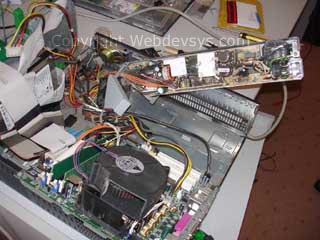
In machine repair
In-machine repair
It is very possible, if not convenient, to repair the PSU whilst still attached to the rest of the system. It only needs to be partially removed. It removes the necessity to disconnect and reconnect cables. Very suited to bulk repair jobs.

If using this method, it is highly recommended that you use some type of current-limiting device when testing. The 'series light bulb' trick works quite nicely, especially when you have a unit which can switch in or out several light bulbs to increase/decrease the resistance.

Commonly failed components

If after replacing the above, the PSU still fails to start (or runs for only a split second), the following should be checked:

Usually the 5v standby circuitry survives. It is on its own self-contained board labelled 'Footlong +5V AUX daughterboard'. If it fails, usually the integrated switcher IC is the culprit. Can only be replaced with part from 'Power Integration', TOP244P.

The secondary (isolated) side of the PSU almost always survives a fault, unless something silly was done, such as shorting the outputs.
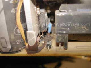
Glue that has carbonised
Horrid glue surrounding the Gate, Drain & Source pins
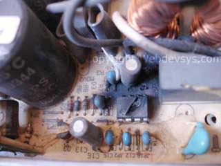
The destroyed components
Blown up - the UC3845B controller IC


Have a 'How do I get this part' Question? Don't ask!

Please don't ask me how or where you can obtain the parts mentioned above. If you are qualified to undertake the repairs, it is assumed that you already know where to source the parts. I'm sure an internet search will yield some good suppliers.

If you want your PSU repaired professionally, read the page on HP Compaq d530 308617-001 Power supply unit repair. We provide this service at competitive rates.


Comments

monemhabashy, Thu, 14 May 2009 09:14 am: Reply
Warning: This comment is awaiting approval and may be subject to automatic removal if it is deemed to be spam.
best regards

RJLago, Sun, 09 Aug 2009 01:49 am: Reply
Warning: This comment is awaiting approval and may be subject to automatic removal if it is deemed to be spam.
Nice job! I have 2 that blew up, you save me some time. Thanks

madbin, Tue, 22 Sep 2009 03:17 am: Reply
Warning: This comment is awaiting approval and may be subject to automatic removal if it is deemed to be spam.
where can i get to buy component qfa9n90
thanks
murathan, Thu, 29 Jul 2010 06:18 am:
google is your friend....

try ebay.

martin, Wed, 30 Sep 2009 08:30 pm: Reply
Warning: This comment is awaiting approval and may be subject to automatic removal if it is deemed to be spam.
l have replaced all the above named components and in addition removed all the glue, but the psu wount switch.What else can l check.
Please email me at martomukuhaz@yahoo.com.Back down here in kenya..

AAN MUJIOANO, Mon, 14 Dec 2009 08:05 pm: Reply
Warning: This comment is awaiting approval and may be subject to automatic removal if it is deemed to be spam.
have changing all not blaze

Andy, Thu, 31 Dec 2009 05:45 am: Reply
Warning: This comment is awaiting approval and may be subject to automatic removal if it is deemed to be spam.
I just replaced mine per the guide, thanks so much. Only thing is now I get no power at all, do you know why the power supply won't power up? I hold the power button down and still nothing, maybe the new supply is bad too? Is there a way to just test the supply out, without it hooked up to the motherboard? Will it just power up without a load?

Thanks again, awesome guide

Ian Barnes, Sat, 23 Jan 2010 03:44 pm: Reply
Warning: This comment is awaiting approval and may be subject to automatic removal if it is deemed to be spam.
Awesome guide. Got my supply up and running in no time. Could have bought one second hand for approx the cost of the components but would have still had to disassemble it to fix the latent problem with the glue. After replacing the parts the +5VSB rail was fine but the PSU would not power up. Traced this fault to 3x 1N4148 diodes around the UC3845B being short circuit. Relaced these and back in business. Thanks again.

Ian Barnes, Sat, 23 Jan 2010 03:46 pm: Reply
Warning: This comment is awaiting approval and may be subject to automatic removal if it is deemed to be spam.
Andy, the supply will not start unless there are loads on the rails. If you short the ATX PSU enable pin to GND you will see the PSU fan briefly move but then the supply will shut down due to no load.

MXM, Sat, 27 Mar 2010 04:20 am: Reply
Warning: This comment is awaiting approval and may be subject to automatic removal if it is deemed to be spam.
Hey guys, wel i happen to have thousands of these psus so, this page came out great, this is the replacement i look for when i try to fix one, wanted to share:
FQA9N90C->NTE2973
MPS6652->NTE129P
UC3845->NTE7099
817A->NTE3098
:)

MXM, Thu, 08 Apr 2010 12:47 am: Reply
Warning: This comment is awaiting approval and may be subject to automatic removal if it is deemed to be spam.
Me again, I have a problem with one of these PSUs, ive changed everything as listed here but the it still wont work... It doesnt blow up no more :) but it doesnt work either :( ... the only good read i get with A/C plugged is 5v from the daughterboard, thats it.... and if i bridge pin4 to try to boot i get 3.2 v and the 4times red flash, "Psu Failure".... any ideas are very much appreciated.

Thanks!!!

Jarrod, Wed, 02 Jun 2010 03:20 pm: Reply
Warning: This comment is awaiting approval and may be subject to automatic removal if it is deemed to be spam.
If I am getting the 4 blinks on the power light does that mean it is too late to simply remove the glue?

Also, is there somewhere with slightly better images so that if I purchase another used PSU I can pull the glue off before applying power to it?

jaseel pc, Fri, 04 Jun 2010 05:05 pm: Reply
Warning: This comment is awaiting approval and may be subject to automatic removal if it is deemed to be spam.
T0P244P ic on the +5v daughter board are burned please give the solution And how i get the ic

Dan, Thu, 01 Jul 2010 06:56 am: Reply
Warning: This comment is awaiting approval and may be subject to automatic removal if it is deemed to be spam.
Where can we get a diagram for this PS? BullPar@Gmail.com

Fernando Pereira, Tue, 13 Jul 2010 05:29 am: Reply
Warning: This comment is awaiting approval and may be subject to automatic removal if it is deemed to be spam.
I I'm from Portugal and I have a small computer repair shop, but I do have an litle problem with R3 It is close to U1 and C11 mine blow up and I can't get the value of It. Please any help!

My email: fernando@domusplace.com
peter, Mon, 01 Aug 2011 03:27 pm:
R3 is 33 ohm

Mavis, Thu, 29 Jul 2010 03:47 am: Reply
Warning: This comment is awaiting approval and may be subject to automatic removal if it is deemed to be spam.
Where can I find diagrams of this PSU so I can remove the glue and replace the damaged parts? My email is mavis_back@aksteel.com

Thanks.

MXM, Fri, 30 Jul 2010 04:53 am: Reply
Warning: This comment is awaiting approval and may be subject to automatic removal if it is deemed to be spam.
according to my eyes R3 is OR-OR-BK... 33ohms :)

if anyone has got more info on this PSU please share.....

peace.

Calavera, Mon, 02 Aug 2010 07:58 pm: Reply
Warning: This comment is awaiting approval and may be subject to automatic removal if it is deemed to be spam.
I am also looking for schematics of this PSU.

For those who are looking for parts, google is your friend.
I found original FQA9N90C on ebay for 2 dollars each. Very high quality mofset. This was the hardest one for me to find. Others are common in my country.

Regards
Calavera, Mon, 02 Aug 2010 07:59 pm:
venedikli@gmail.com

thanks in advance!

Grigory, Wed, 11 Aug 2010 02:55 pm: Reply
Warning: This comment is awaiting approval and may be subject to automatic removal if it is deemed to be spam.
Do you have schematick diagram?

nalle, Wed, 15 Sep 2010 07:06 am: Reply
Warning: This comment is awaiting approval and may be subject to automatic removal if it is deemed to be spam.
I have three daughter boards not functioning (no 5V output). Components seems to be OK, even replaced opto-component and TOP244P (with TOP244PN) but still nothing. There are high voltage +310V and +70V coming from main board. Might there be some clever feedback circuit I have to look for?

nalle, Fri, 17 Sep 2010 05:17 am: Reply
Warning: This comment is awaiting approval and may be subject to automatic removal if it is deemed to be spam.
Well, solved. When there is 70V on J2 then usually TOP244P is to blame. The daughterboard is giving out 12V to main board (overruling 70V on main board through 150k pull-up resistor). In one case the feedback winding of transformer on daughterboard was broken.
nalle.mae@hot.ee

nalle, Wed, 06 Oct 2010 07:01 am: Reply
Warning: This comment is awaiting approval and may be subject to automatic removal if it is deemed to be spam.
On daughter board with burned TOP244 check also 6V zener diode D61 on secondary side of board. Its function is obviously to protect against overvoltage.

dskum, Wed, 06 Oct 2010 12:24 pm: Reply
Warning: This comment is awaiting approval and may be subject to automatic removal if it is deemed to be spam.
Did anyone manage getting a schematic for this unit?

dskum, Fri, 08 Oct 2010 12:46 pm: Reply
Warning: This comment is awaiting approval and may be subject to automatic removal if it is deemed to be spam.
Does anyone know what is the Diode which connects to pin 6 of the UC3845BN? Mine was broken due to spark and cannot identify. There is no reference design where I can find the value

rajesh, Mon, 11 Oct 2010 03:15 am: Reply
Warning: This comment is awaiting approval and may be subject to automatic removal if it is deemed to be spam.
circute digram
dskum, Tue, 26 Oct 2010 01:20 pm:
Do you have the Circuit Diagram?

dskum, Tue, 26 Oct 2010 01:19 pm: Reply
Warning: This comment is awaiting approval and may be subject to automatic removal if it is deemed to be spam.
Can anyone please let me know what is D4. Its connected to Pin 1 of UC3845B.

Also the page 13 of the following gives a basic reference design. (Its not same, but close)

http://www.datasheetdir.com/UC3845B+download

Any help for D4 will be appreciated.

Thanks

MXM, Tue, 09 Nov 2010 10:21 am: Reply
Warning: This comment is awaiting approval and may be subject to automatic removal if it is deemed to be spam.
hey, D4 on the PSUs i got around reads: PH 41 48

if u ask me, thats a regular 1n4148 diode... i would use whatever diode u use as replacement for the other diodes around ic3845.... nothing fancy....i do not have schematics, if anybody has got more info on this psu please share....

peace.

dskum, Sun, 21 Nov 2010 04:40 pm: Reply
Warning: This comment is awaiting approval and may be subject to automatic removal if it is deemed to be spam.
Thanks MXM.

I replaced some 5 components and the power supply in running now. (motherboard properly powers up and running, but it powers on as soon as mains connected. The power supply wont respond to Computer's power signal.)

troth530, Sun, 19 Dec 2010 06:16 am: Reply
Warning: This comment is awaiting approval and may be subject to automatic removal if it is deemed to be spam.
Hi, I'm doing a preventative maintenance and cannot find U2 and U3 opto couplers. I think I'm looking for a couple of 6 or 8 pin DIP package, but I've looked almost everywhere (including the daughterboards) and cannot seem to locate. Please point me in the right direction, like near fan or so many inches from back, etc... Thanks in advance. Tim

dskum, Sun, 19 Dec 2010 03:49 pm: Reply
Warning: This comment is awaiting approval and may be subject to automatic removal if it is deemed to be spam.
The optocoupler are the 4 Pin DIP package. The power supply has the EL-816. Similar to this but this one has lower breakdown voltage.. but good enought for this replacement IMO and is available for cheap at fleabay

http://www.datasheetarchive.com/pdf-datasheets/Datasheets-10/DSA-195117.html

dskum, Sun, 19 Dec 2010 03:51 pm: Reply
Warning: This comment is awaiting approval and may be subject to automatic removal if it is deemed to be spam.
Also may be you need to remove the 5VSB daughter board to access these OCs.

Cornboats, Fri, 24 Dec 2010 08:44 pm: Reply
Warning: This comment is awaiting approval and may be subject to automatic removal if it is deemed to be spam.
Great help and a good read. From what I understand you can't power this up for testing unconnected.
On mine resistors R54 & R53 have blown . Can't read the values. Anyone have a look at theres please and let me know.

DCornelissen@talktalk.net

kingash, Wed, 29 Dec 2010 03:50 am: Reply
Warning: This comment is awaiting approval and may be subject to automatic removal if it is deemed to be spam.
I have replaced all the faulty parts but the psu cannot power on. I get the 5V from the daughter-board. I have 5 of these PSUs behaving the same way. I had managed to fix some 4 more but these ones had their fuses intact. The ones that are not working had blown fuses.

What goes together with the fuse.

Regards
kingatua@thikahighway.com

kingash, Wed, 29 Dec 2010 03:55 am: Reply
Warning: This comment is awaiting approval and may be subject to automatic removal if it is deemed to be spam.
On measuring the TOP244PN IC, I find that all the grounded pins to be shored (4 pins)when out of circuit. Is this the design or could the IC be blown shorting.

Regards
kingatua@thikahighway.com

Padmanabhan D, Mon, 15 Aug 2011 03:34 pm: Reply
Warning: This comment is awaiting approval and may be subject to automatic removal if it is deemed to be spam.
Hi, i have a compaq slim desktop, its smps with series PDP-124 is under fault condition, where can i get the spares. pl reply its urgent

UGeorge, Thu, 08 Sep 2011 12:35 am: Reply
Warning: This comment is awaiting approval and may be subject to automatic removal if it is deemed to be spam.
How about preventive maint?

I had one (power mosfet) go like ur picture showed.

Should I remove the glue, if that possible? With what? Replace glue with what?

Kludge, Thu, 22 Sep 2011 12:08 am: Reply
Warning: This comment is awaiting approval and may be subject to automatic removal if it is deemed to be spam.
Got a failed one on the bench.... replaced U1, R5,
R9 and R11, all of which were bad. On my unit, R5 appeared to be a 10K resistor instead of 1K.

Replaced the mosfet with a STW11NK90Z which was the only 900V one in the junk box, but which looks to be a good equivalent.

The supply does not fire up, and I measure 4.37V on the current sense pin of the U1, which is shutting U1 down as soon as it goes over 1V. What else can be going wrong with the current sense section besides R11 and R5 going wrong?
Is it the MOSFET sub?

U2 tests as being okay (well, at least it's not a dead short, and it tests like a pair of diodes), and U2 is clearly the voltage feedback isolator. But where is U3 and what is it? From your description it's an optoisolator but I cannot find the thing on this very cluttered board.

Robert, Tue, 22 Nov 2011 08:19 am: Reply
fixed several, remaining ones won't start and two
have a single bad voltage shutdown error. Finally cross referenced the scy99112 = tsm112 = ncp112.
+3.3v +5v +12v voltage monitor / supervisor and the ka358 is dual op-amp in sip package.
Swapping the shortboard doesn't change anything.
I swapped the pwm front ends into others to fix the other ones.

ADRIAN, Wed, 23 Nov 2011 08:18 am: Reply
COMO LA PRENDO SIN TENER QUE CONECTAR LA MODER BOARD
...
nO SE SI LA TARJETA ESTE DAÑADA PORQUE CADA VEZ QUE LA CONECTO TRUENA ...?????

Anonymous, Wed, 23 Nov 2011 10:57 am: Reply
POORLY translated as: AS THE EXCEPTIONAL WITHOUT HAVING TO CONNECT THE MODERN JUNTA ... don't know if the CARD THIS ENCLOSURE damaged because every time the connected THUNDERS ... ???

ASSUMING your asking about shortboard. The entire computer shuts down with one missing voltage error. Looks like the power monitor is controlling the PSU shutdown...

Cesar, Wed, 23 Nov 2011 12:12 pm: Reply
That is the resistance value R7 (FQA 9N90C gate)?

Robert, Thu, 24 Nov 2011 10:22 am: Reply
R7 & R8 (both 4.7k) looks like a standard divider network. I've built a multitester for the opto-isolators and found a couple of those bad, also.
No tester for the TOP224 yet. I would like to have an actual schematic, instead of the many UC3845 / UC3842 partials comparison. Still waiting for 3845's and 3842's didn't work. Not the timing but the voltage turnon difference...

Robert, Thu, 24 Nov 2011 10:36 am: Reply
... and to physically check, R9 (22 ohm) goes to the gate of the mosfet from the 3845...

Robert, Sun, 27 Nov 2011 06:17 am: Reply
searching the datasheets, there's one for: TOP242-250, having a partial PC board layout(s) for testing several different top chips. These didn't finish the secondary side for any positive functional output or idiot light. At this point, I would prefer a low cost test board.

...Bumb...

evident Computers, Tue, 06 Dec 2011 11:19 pm: Reply
Thanks man it really help

hugo, Mon, 20 Feb 2012 02:13 am: Reply
I check de R11 i'ts suppose to be 24 Ohmns and when I desolder of board, I have 5 Ohmns in my multimeter.
This resistance have to see for current sense of 3845B IC.
brelgi, Wed, 22 Feb 2012 09:51 am:
the value for R11 is .24 ohms

rafael, Mon, 27 Feb 2012 09:55 am: Reply
Help me please with next ID`s devices: U5,R4 and R5 thanks.

robert, Wed, 11 Apr 2012 08:26 am: Reply
yep, the "no +5vsb" is actually 12vdc below tolerance @ 11.87vdc

steve from Hungary, Wed, 11 Apr 2012 08:17 pm: Reply
Hello!
To test, put some load on 3,3V (e.g. 12V car bulb), because the voltage regulator (TL451) works on 3,3V line. If this line is not loaded, the supervisory circuit switch off the supply after short time. To temporary disable this, you can put a short circuit on primary side of the optocoupler (near U2). My unit has TL451 self oscillating. After change, everything works ok!

robert, Mon, 16 Apr 2012 11:19 am: Reply
U5 is TOP244, on the +5 STBY Longboard. R4 is 2.2k and R5 is 1k, both on the mainboard.

robert, Fri, 20 Apr 2012 06:04 pm: Reply
nope, the adjustable zeners are TL431.

getting close to finishing a schematic, might need some proof reading.
maybe second person check...
Don, Wed, 19 Nov 2014 08:26 am:
Robert, I would like to help by checking your schematic. I have a dead power supply and have found datasheets for most of the semiconductors.
I'm a retired electronics circuit design engineer.
I prefer to use the free schematic drawing software from ExpressPCB.
Don

robert, Sat, 21 Apr 2012 04:27 am: Reply
modified ATX power tester for +5 Standby power LED, which says the +5 longboard is good. this wasn't same indicator as power good indicator labelled +5stby, which can be out.

robert, Sat, 21 Apr 2012 04:30 am: Reply
substitute mosfets can be tricky, having just ordered to volt & amp specification and finding
thermal specification requirements fail.

those worked for benchtest but not long for full computer load

robert, Sat, 21 Apr 2012 04:39 am: Reply
can make an opto-isolator tester, schematic on internet. fixed up several, having found & replaced faulty optos...

robert, Mon, 14 May 2012 06:16 pm: Reply
whats a good price for unproofed schematic?

have to put that disclaimer on it, i.e. anything

you do is on you, alone.

Konstantin, Fri, 01 Feb 2013 08:26 am: Reply
I have device with died U1. Thanks for typing!

credit loans, Wed, 19 Jun 2013 01:18 am: Reply
Comment posted from IP Address 46.161.41.63 has been hidden.

Rizwan, Sun, 01 Dec 2013 07:56 pm: Reply
light flashing red 5 time and beep...

Uwe, Mon, 22 Sep 2014 02:12 am: Reply
Could anybody tell my what kind of sparepart was that "blown up", in photo - "Blown up - the UC3845B controller IC".
Thanks for your help Uwe

Don, Fri, 21 Nov 2014 01:53 am: Reply
Is there a way that I can post a schematic attachment as a pdf file, or do I need to look for a different forum?

Don, Sat, 22 Nov 2014 09:30 am: Reply
Here is a schematic of the Power Good Monitor daughter board. I will post more schematics as soon as I have finished drawing them.

https://www.dropbox.com/s/tr1enc0i2aubnwi/PDP124P-3.pdf?dl=0
Don, Sun, 23 Nov 2014 03:21 am:
Update,
Here is a link to my Dropbox folder that has my PDP124P drawings. More schematics will be added to this folder as they become available.
Disregard the previous link.

https://www.dropbox.com/sh/bamvvcypfego3sm/AADVSj5NLXpoi7sSjkeF_vs0a?dl=0

rotich, Thu, 28 Jan 2016 07:03 am: Reply
i need to know the values of D6 and R12 in the aux daughter board mine burnt up

BigAF, Thu, 02 Mar 2017 08:01 pm: Reply
Don, thank you for the work on the schematic, awesome information. Saved more than one headache on the adventure to converting the pdp124p into a bench top power supply for circuit design and analysis. Thank you again for the time and effort put in on these schematics.
BigAF

Anonymous, Tue, 11 Dec 2018 11:19 pm: Reply
Thank you for this share

AbdulHaseeb, Thu, 13 Dec 2018 08:06 am: Reply
Mine got fixed the issue by replacing R54(10ohm)1watt. It took 4days to identify the culprit resistor, Since there are no burn signs.

RailGun, Fri, 21 Jun 2019 11:30 pm: Reply
I have changed the U1 (UC3845BN), because it was blowed up. The D2 and D3 was in short circuit, so I've changed those, too. JP4 was melted, I replaced.
When connecting to power, U1 blowed up again!

What could be the problem?

Ashish Dogra, Fri, 26 Mar 2021 03:50 am: Reply
hello i have compaq PDP123P power supply 240W max.
i am facing one very diffrent problem when i short green wire with black wire(Negative)the fan give a little responce and after two three times short the supply gets on but the 12v is gives 9volts output.I searched so many parts burnt or circuit diagram but unfortunately i can't found anything.So please help me to solve this my problem.Thanks
ashish_dogra2001@hotmail.com

Rafiq, Wed, 15 Dec 2021 10:17 pm: Reply
Please send IC chip nomber on foot long+5v Aux Daughter board on U5
Reply on
rafiqshaheen561@gmail.com

lady gaga, Sat, 24 Jun 2023 10:28 pm: Reply
how can i power on it?.i trying to make a short between green wire and black wire, but didn't power on.

  Add a comment


Your name:

Comment:

Verification code:
Verification Code Type the letters and numbers that you see.