Articles > PDP124P repair notes
I have put together a few bits of information useful for repairing d530 SFF PSUs. Please note that this is technical material, and not intended for most end-users. However, if you have the skills in SMPS repair (or electronics in general), this information might help.
As usual, disclaimers apply. After all, this information is on the internet. Use your own judgment and common sense. If you destroy your PSU, computer, or even burn down your house, it's your own fault.
In-machine repair
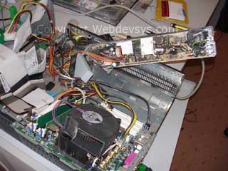
In-machine repair It is very possible, if not convenient, to repair the PSU whilst still attached to the rest of the system. It only needs to be partially removed. It removes the necessity to disconnect and reconnect cables. Very suited to bulk repair jobs.
If using this method, it is highly recommended that you use some type of current-limiting device when testing. The 'series light bulb' trick works quite nicely, especially when you have a unit which can switch in or out several light bulbs to increase/decrease the resistance.
Commonly failed components
- MOSFET: 900v 9A N-Channel. Can be Toshiba 2SK2611, 2SK3548, Fairchild FQA9N90C or equivalent
- Q3, Q2: replace with PNP 60V 500mA MPS6652 or equivalent
- U1: UC3845B / UC3845BN PWM controller chip
- R5: 1K ohm (couples U1 to current sense)
- R9: 22 Ohm (MOSFET Gate coupler to 3845B (U1) output drive)
- R11: 0.22 ohm, between MOSFET source and -ve rail, used for current sense by U1
- U2, U3: Opto coupler. Sometimes they both survive. Usually one fails (permanently conducting primary side).
- Fuse: T5A 250v M205. Ceramic sand-filled type. Can be replaced with a glass fuse, but less safe (potential for glass shards when it blows).
If after replacing the above, the PSU still fails to start (or runs for only a split second), the following should be checked:
- D2 & D3: 1N4148 - can go short circuit, preventing the feedback loop signal from reaching the UC3845BN
Usually the 5v standby circuitry survives. It is on its own self-contained board labelled 'Footlong +5V AUX daughterboard'. If it fails, usually the integrated switcher IC is the culprit. Can only be replaced with part from 'Power Integration', TOP244P.
The secondary (isolated) side of the PSU almost always survives a fault, unless something silly was done, such as shorting the outputs.
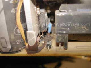
Horrid glue surrounding the Gate, Drain & Source pins
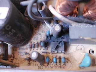
Blown up - the UC3845B controller IC
Have a 'How do I get this part' Question? Don't ask!
Please don't ask me how or where you can obtain the parts mentioned above. If you are qualified to undertake the repairs, it is assumed that you already know where to source the parts. I'm sure an internet search will yield some good suppliers.
If you want your PSU repaired professionally, read the page on HP Compaq d530 308617-001 Power supply unit repair. We provide this service at competitive rates.
RJLago, Sun, 09 Aug 2009 01:49 am: Reply
madbin, Tue, 22 Sep 2009 03:17 am: Reply
martin, Wed, 30 Sep 2009 08:30 pm: Reply
AAN MUJIOANO, Mon, 14 Dec 2009 08:05 pm: Reply
Andy, Thu, 31 Dec 2009 05:45 am: Reply
Ian Barnes, Sat, 23 Jan 2010 03:44 pm: Reply
Ian Barnes, Sat, 23 Jan 2010 03:46 pm: Reply
MXM, Sat, 27 Mar 2010 04:20 am: Reply
MXM, Thu, 08 Apr 2010 12:47 am: Reply
Jarrod, Wed, 02 Jun 2010 03:20 pm: Reply
jaseel pc, Fri, 04 Jun 2010 05:05 pm: Reply
Dan, Thu, 01 Jul 2010 06:56 am: Reply
Fernando Pereira, Tue, 13 Jul 2010 05:29 am: Reply
Mavis, Thu, 29 Jul 2010 03:47 am: Reply
MXM, Fri, 30 Jul 2010 04:53 am: Reply
Calavera, Mon, 02 Aug 2010 07:58 pm: Reply
Grigory, Wed, 11 Aug 2010 02:55 pm: Reply
nalle, Wed, 15 Sep 2010 07:06 am: Reply
nalle, Fri, 17 Sep 2010 05:17 am: Reply
nalle, Wed, 06 Oct 2010 07:01 am: Reply
dskum, Wed, 06 Oct 2010 12:24 pm: Reply
dskum, Fri, 08 Oct 2010 12:46 pm: Reply
rajesh, Mon, 11 Oct 2010 03:15 am: Reply
dskum, Tue, 26 Oct 2010 01:19 pm: Reply
MXM, Tue, 09 Nov 2010 10:21 am: Reply
dskum, Sun, 21 Nov 2010 04:40 pm: Reply
troth530, Sun, 19 Dec 2010 06:16 am: Reply
dskum, Sun, 19 Dec 2010 03:49 pm: Reply
dskum, Sun, 19 Dec 2010 03:51 pm: Reply
Cornboats, Fri, 24 Dec 2010 08:44 pm: Reply
kingash, Wed, 29 Dec 2010 03:50 am: Reply
kingash, Wed, 29 Dec 2010 03:55 am: Reply
Padmanabhan D, Mon, 15 Aug 2011 03:34 pm: Reply
UGeorge, Thu, 08 Sep 2011 12:35 am: Reply
Kludge, Thu, 22 Sep 2011 12:08 am: Reply
Robert, Tue, 22 Nov 2011 08:19 am: Reply
ADRIAN, Wed, 23 Nov 2011 08:18 am: Reply
Anonymous, Wed, 23 Nov 2011 10:57 am: Reply
Cesar, Wed, 23 Nov 2011 12:12 pm: Reply
Robert, Thu, 24 Nov 2011 10:22 am: Reply
Robert, Thu, 24 Nov 2011 10:36 am: Reply
Robert, Sun, 27 Nov 2011 06:17 am: Reply
evident Computers, Tue, 06 Dec 2011 11:19 pm: Reply
hugo, Mon, 20 Feb 2012 02:13 am: Reply
rafael, Mon, 27 Feb 2012 09:55 am: Reply
robert, Wed, 11 Apr 2012 08:26 am: Reply
steve from Hungary, Wed, 11 Apr 2012 08:17 pm: Reply
robert, Mon, 16 Apr 2012 11:19 am: Reply
robert, Fri, 20 Apr 2012 06:04 pm: Reply
robert, Sat, 21 Apr 2012 04:27 am: Reply
robert, Sat, 21 Apr 2012 04:30 am: Reply
robert, Sat, 21 Apr 2012 04:39 am: Reply
robert, Mon, 14 May 2012 06:16 pm: Reply
Konstantin, Fri, 01 Feb 2013 08:26 am: Reply
credit loans, Wed, 19 Jun 2013 01:18 am: Reply
Rizwan, Sun, 01 Dec 2013 07:56 pm: Reply
Uwe, Mon, 22 Sep 2014 02:12 am: Reply
Don, Fri, 21 Nov 2014 01:53 am: Reply
Don, Sat, 22 Nov 2014 09:30 am: Reply
rotich, Thu, 28 Jan 2016 07:03 am: Reply
BigAF, Thu, 02 Mar 2017 08:01 pm: Reply
Anonymous, Tue, 11 Dec 2018 11:19 pm: Reply
AbdulHaseeb, Thu, 13 Dec 2018 08:06 am: Reply
RailGun, Fri, 21 Jun 2019 11:30 pm: Reply
Ashish Dogra, Fri, 26 Mar 2021 03:50 am: Reply
Rafiq, Wed, 15 Dec 2021 10:17 pm: Reply
lady gaga, Sat, 24 Jun 2023 10:28 pm: Reply